Connecting three local networks via WireGuard VPN
In this example, we'll show how to set up a Wireguard connection between three Keenetic routers so that the hosts in their local segments can communicate. This connection scheme is called Site-To-Site VPN (e.g., inter-office communication to expand network infrastructure).
It is necessary to ensure that the external WAN IP address of one of the routers is accessible from the others. If the VPN tunnel is to be built over the Internet, it means that one of the routers must have a public IPv4 address provided by the ISP.
Install the WireGuard VPN system component. You can do this in the web interface on the General System Settings page under KeeneticOS Update and Component Options by clicking on Component options.

The Wireguard VPN component must be installed on all three Keenetic routers. After that, Wireguard VPN settings will appear in the web interface on the Other Connections page.
Let's look at the graphical network diagram:
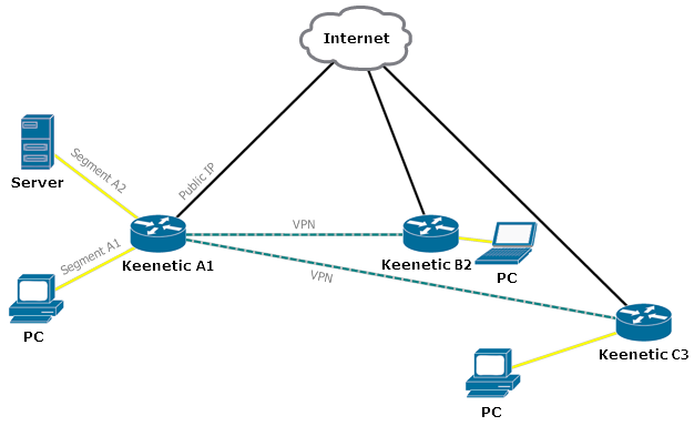
Keenetic Router A1 has a public WAN IP address given by the ISP. Routers B2 and C3 will connect to this address. In other words, the Wireguard interface on Router A1 will act as a server to which the client routers of remote offices B2 and C3 connect.
There are two local segments in the Keenetic Router A1 local network: A1 and A2. These need to be accessed from the local network of router B2. In the opposite direction, to the local network C3, access should also be provided from these two segments.
The LAN behind the Keenetic Router C3 should only have access to segment A1 on the Keenetic A1 network.
Hosts on remote networks B2 and C3 should also be able to exchange traffic.
In our example, we use the private IP address
192.168.201.14as the public WAN IP address issued by the ISP to Router A1. Generally speaking, the network environment to which all three routers are connected (black lines in the diagram) is not necessarily global; it can also be the ISP's local network.Let's use Router A1 as a server and assume it is located in the head office, while the two remote networks are branches B2 and C3. On the Keenetic Router A1, the subnet of the A1 segment is
192.168.111.1/24, and the subnet of the A2 segment is192.168.112.1/24. The local network of branch office B2 is192.168.15.1/24, and the local network of branch office C3 is192.168.26.1.24.Router
Local network
Have access to
Tunnel interface address
Keenetic A1 (Head office)
192.168.111.1/24
B2, C3
172.16.82.1/24
192.168.112.1/24
B2
Keenetic B2 (Branch 2)
192.168.15.1/24
А1, А2, C3
172.16.82.2/24
Keenetic C3 (Branch 3)
192.168.26.1/24
А1, B2
172.16.82.3/24
First, configure WireGuard VPN connections on Routers A1 and B2.
3.1. Preliminary configuration of the Keenetic Router B2.
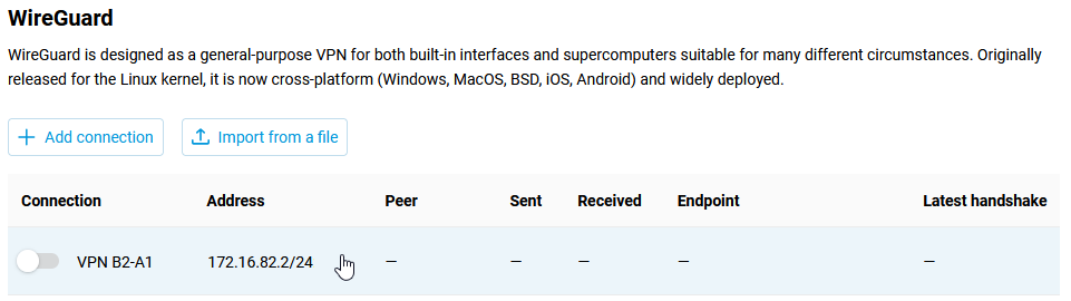
In the Internet → Other Connections menu, in the Wireguard section, click the Add connection button. The settings window will open, in which you should specify the name of the tunnel:
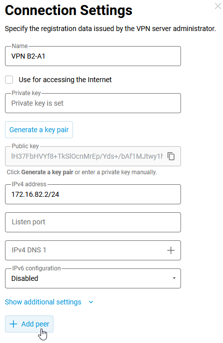
VPN B2-A1. Using the Generate a key pair button, you should create a pair of keys, private and public, which will be used to secure the connection.In the IPv4 address field, specify the IP address in
IP/bitmaskformat:172.16.82.2/24(this is the internal ‘technical’ address of the tunnel). You can use another subnet, but it should be selected from the ranges reserved for private use to avoid overlapping with other subnets configured on these devices. Next, save the public key to the clipboard (you will need it in the next step) and then click Save to apply the settings.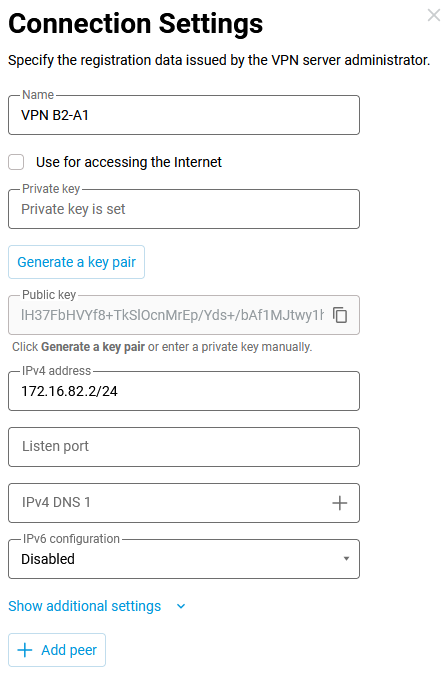
3.2. Configuration of the Keenetic Router A1 (connection to branch B2).
On the Router A1, you need to add a connection, specify a name and generate a pair of keys in the same way. You don't need to copy Router A1's public key to the clipboard yet.
Next, let's set the address. It makes sense to specify the internal ‘
technical’ address of the device in the tunnel from the subnet already chosen when configuring the interface on Router B2 — on it, we specified the address from the network172.16.82.2/24, on Router A1, the address should be specified from the same network. Let's set the address172.16.82.1/24at the end of the Keenetic A1 tunnel.Note
The address can be specified with a
32-bitmask, i.e. not the network address but the host address. In this case, you will have to add a route pointing to the tunnel interface network or individually to each end of the tunnel. If you specify the address so that the mask covers the addresses of all peers of the tunnel, the automatically generated route eliminates the need to manually enter the setting data.The port specified in the Listen port field will be used in further configuration of Router B2. This port will be used by Keenetic B2 and Keenetic C3 routers when establishing a VPN tunnel. In our example, we will use port number
16632. Router A1 will automatically open this port on all interfaces to allow incoming connections, and there is no need to add additional allow rules in the firewall.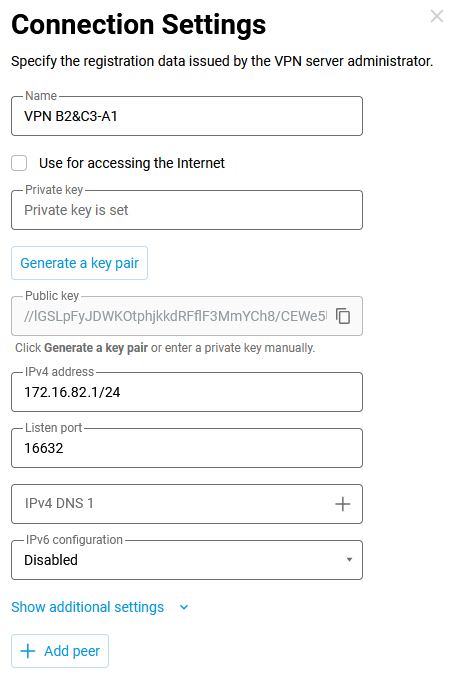
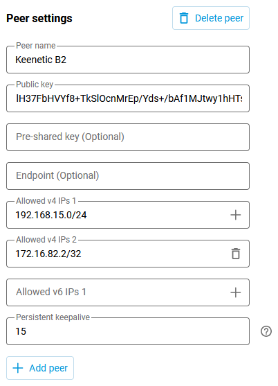
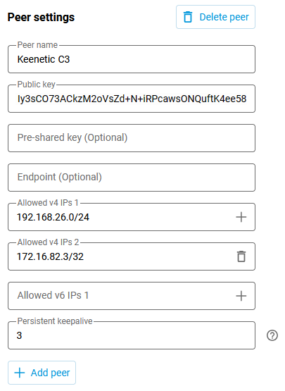
Next, add a connection using the Add peer button. Specify the appropriate connection name and the public key of the tunnel from Router B2. Since this key was copied to the clipboard in the previous step, it can now be pasted into the Public key field.
In the Allowed IPs fields, you must specify the addresses from which traffic from a remote party should be allowed and the addresses to which traffic can be sent to a remote party. These are: the technical address of the remote end of the tunnel -
172.16.82.2/32(from the peer B2 side the traffic in the tunnel will go with the source address172.16.82.2, and in our example we specify here explicitly the host address, taking into account that the address spaces of allowed subnets on connections within one interface should not overlap), and the remote network - the local network of Router B2 -192.168.15.0/24(this network should be accessible through the tunnel).In the Persistent keepalive field, you must specify the periodicity of probing attempts. This is an internal, built-in protocol check of the remote side connection availability. Usually, an
8-10second interval between checks is sufficient.After that, copy the public key of Router A1 to the clipboard and save the configuration.
3.3. Now, perform further configuration of the connection on Router B2. You need to add a connection that will be opened to Router A1.
Click on the tunnel entry, a window will open with its settings, click on Add peer.
In the peer settings, we specify the Peer name (in our example, Keenetic A1), Public key (copied to the clipboard in the previous step), Endpoint in the
IP:portformat (this is the public WAN IP address of Router A1 and the listening port, which was specified during the tunnel configuration on Router A1), in our example192.168.201.14:16632.In the Allowed IPs field, we need to add the addresses of the remote ends of the tunnel. We specify
172.16.82.0/24, traffic from the addresses of this network will be accepted from the tunnel. Let's add the network addresses of local segments A1 and A2 of Keenetic Router A1 -192.168.111.0/24and192.168.112.0/24. Outgoing traffic to these two networks will be allowed to pass through the tunnel. Let's add the addresses of the branch office C3 local network,192.168.26.0/24— this network also requires access. We'll select 10 seconds for the activity check interval on this side. Save the settings.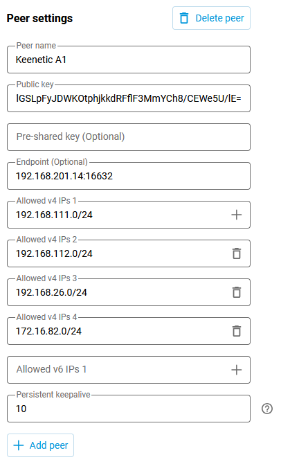
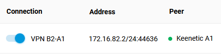
3.4 Switch on the configured VPN interfaces on Routers A1 and B2. If everything is configured correctly, a green connection status indicator should be displayed in the Peer column.
Keenetic А1:
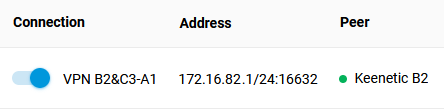
Keenetic B2:
Setting up the Firewall and Static routing. his will require specifying routes and allowing incoming traffic to the added VPN interfaces.
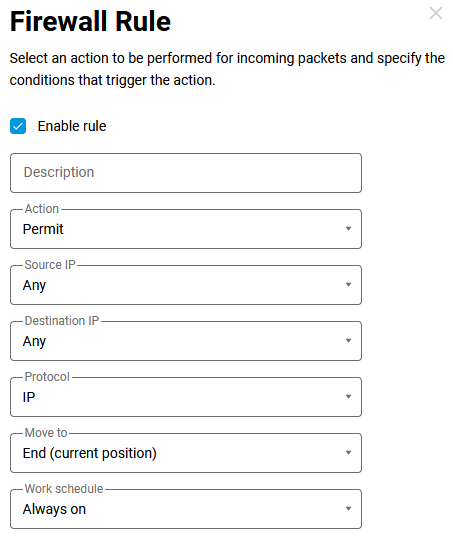
4.1. We are allowing incoming traffic to the Wireguard interface. This should be done because, by default, the tunnel interfaces are set to a public security level and incoming traffic is denied. To allow requests from remote networks to pass through the tunnel, add the corresponding setting to the Firewall menu on both routers.
4.2 The 'technical' addresses of the network designated at the ends of the tunnel —
172.168.82.1and172.16.82.2— can already exchange data at this stage. To send traffic through the tunnel to the remote networks required by the diagram, it is necessary to add routes on the routers (Routing menu → Create route button).Keenetic A1 — route to the
192.168.15.0/24network through the tunnel: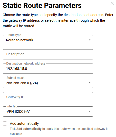
Keenetic B2 - routes to networks
192.168.111.0/24,192.168.112.0/24and192.168.26.0/24through the tunnel: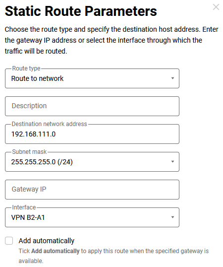
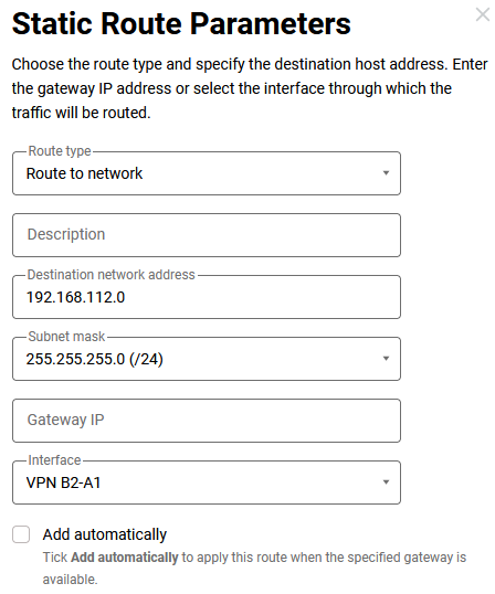
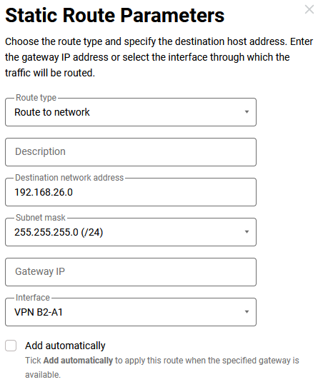
The last route cannot work yet, as the connection to the branch office C3 is not yet configured. Let's complete the configuration.
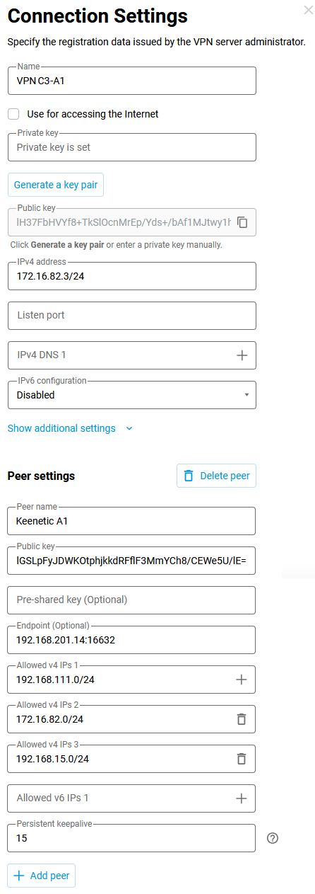
Setting up the connection between Keenetic A1 and C3. The procedure is the same as in steps
3and4. You will need the public key from Router A1. Copy it to the clipboard and configure the Wireguard interface in Router C3.5.1. Keenetic C3:
Wireguard interface settings.
Configuring the network screen for the WireGuard interface.
Routing rules.

5.2. Keenetic А1:
Now, add the C3 office peer to the configured Wireguard interface.
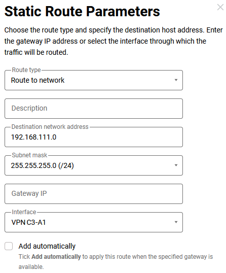
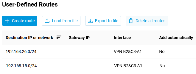
It is also needed to specify the route to the
192.168.26.0/24network (on Router B2, we have already added this setting, now it will work — after turning on the interface in office C3).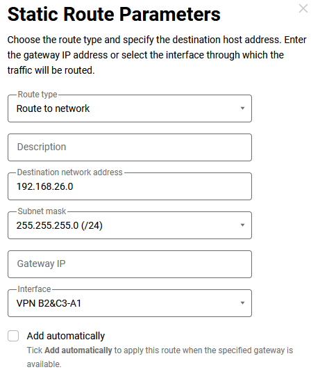
The configuration is now complete.
For testing purposes, you can ping hosts of the remote networks directly from the routers through the Diagnostics menu, according to the diagram (p. 2).
Below are the final configurations of the three routers.
Keenetic А1:
access-list _WEBADMIN_Wireguard0
 permit ip 0.0.0.0 0.0.0.0 0.0.0.0 0.0.0.0
interface Wireguard0
 description "VPN B2&C3-A1"
 security-level public
 ip address 172.16.82.1 255.255.255.0
 ip access-group _WEBADMIN_Wireguard0 in
 ip tcp adjust-mss pmtu
 wireguard listen-port 16632
 wireguard peer lH37FbHVYf8+TkSlOcnMrEp/Yds+/bAf1MJtwy1hHTs= !Keenetic B2
 keepalive-interval 15
 allow-ips 192.168.15.0 255.255.255.0
 allow-ips 172.16.82.2 255.255.255.255
 !
 wireguard peer Iy3sCO73ACkzM2oVsZd+N+iRPcawsONQuftK4ee58kM= !Keenetic C3
 keepalive-interval 3
 allow-ips 192.168.26.0 255.255.255.0
 allow-ips 172.16.82.3 255.255.255.255
 !
 up
ip route 192.168.15.0 255.255.255.0 Wireguard0
ip route 192.168.26.0 255.255.255.0 Wireguard0
Keenetic B2:
access-list _WEBADMIN_Wireguard0
 permit ip 0.0.0.0 0.0.0.0 0.0.0.0 0.0.0.0
interface Wireguard0
 description "VPN B2-A1"
 security-level public
 ip address 172.16.82.2 255.255.255.0
 ip access-group _WEBADMIN_Wireguard0 in
 ip tcp adjust-mss pmtu
 wireguard peer //lGSLpFyJDWKOtphjkkdRFflF3MmYCh8/CEWe5U/lE= !Keenetic А1
 endpoint 192.168.201.14:16632
 keepalive-interval 10
 allow-ips 192.168.111.0 255.255.255.0
 allow-ips 192.168.112.0 255.255.255.0
 allow-ips 192.168.26.0 255.255.255.0
 allow-ips 172.16.82.0 255.255.255.0
 !
 up
ip route 192.168.111.0 255.255.255.0 Wireguard0 ip route 192.168.112.0 255.255.255.0 Wireguard0 ip route 192.168.26.0 255.255.255.0 Wireguard0
Keenetic C3:
access-list _WEBADMIN_Wireguard0
 permit ip 0.0.0.0 0.0.0.0 0.0.0.0 0.0.0.0
interface Wireguard0
 description "VPN C3-A1"
 security-level public
 ip address 172.16.82.3 255.255.255.0
 ip access-group _WEBADMIN_Wireguard0 in
 ip tcp adjust-mss pmtu
 wireguard peer //lGSLpFyJDWKOtphjkkdRFflF3MmYCh8/CEWe5U/lE= !Keenetic А1
 endpoint 192.168.201.14:16632
 keepalive-interval 15
 allow-ips 172.16.82.0 255.255.255.0
 allow-ips 192.168.111.0 255.255.255.0
 allow-ips 192.168.15.0 255.255.255.0
 !
 up
ip route 192.168.111.0 255.255.255.0 Wireguard0 ip route 192.168.15.0 255.255.255.0 Wireguard0